At first I bought the Chinese airband receiver kit and assembled. After then I remodeled it with Si5351a VFO local oscillator. And I used Si5351a VFO local oscillator for Si4732 radio.

The R909-DSP is composed with the VFO-PCB of Si5351a and the RF-PCB of Si4732.
This time I diverted the VFO-PCB for the Chinese airband receiver kit.
This is the assembled PCB.

Please look at the brock diagram below.
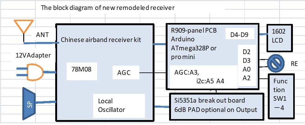
I installed the both PCBs in YM-180 case. There is VFO-PCB on left side and RF-PCB on right side.

Combining the VFO-PCB of Si5351a controled by Arduino, the Chinese airband receiver kit was reborn as a stable scanner. I also adopted the 10.7MHz crystal band pass filter and the noise less switch muting circuit of LM386.
So I could incorpolate the 8.333kHz channel spacing.
If you are interested in detail, please find the schematic and the BOM of VFO-PCB.
If you would like to follow the experimant, I will show you the PCB zip file and the sketch. At that case you shall get PCBGOGO ID resistration through the below site freely and tell me the ID number via mail. My mail is "nobcha48 at gmail.com".
Gerber files od the PCB
Please resister PCBGOGO via URL, when you use this files.
If you would like to refer the sketch, please let me to know via mail.
nobcha48 at gmail.com